English
English
English
Centrifugal pumps are hydraulically operated machines characterized by their ability to transfer energy to liquids (especially liquids) through the action of a centrifugal force field. Their main purpose is to transfer liquid through increasing pressure. Centrifugal pumps can have different constructions, but their principle of operation and dynamic characteristics are always the same.
Schematically, a centrifugal pump is made up of an impeller that rotates inside the pump body. The impeller consists of a series of impellers, preferably of a radial design, that impart kinetic energy to the pumped liquid. Pump body equipped with suction and discharge mouths for the pumped liquid. The suction mouth has an axis corresponding to the axis of rotation of the impeller, and the discharge mouth has an axis normal to the impeller shaft, but still lies on a plane passing through its own axis.
The pumped liquid enters continuously through the pump's suction mouth at the center of the impeller. From here, it is accelerated in a radial direction all the way to the edge of the impeller, where it exits the housing.
The fluid flow is accelerated by the thrust that the impeller blades, by virtue of their curvature, impart to the fluid flow itself. In this way, the liquid gains energy, mainly in the form of an increase in its average speed (kinetic energy). Inside the pump body, the liquid is slowed down appropriately thanks largely to the direction of motion.
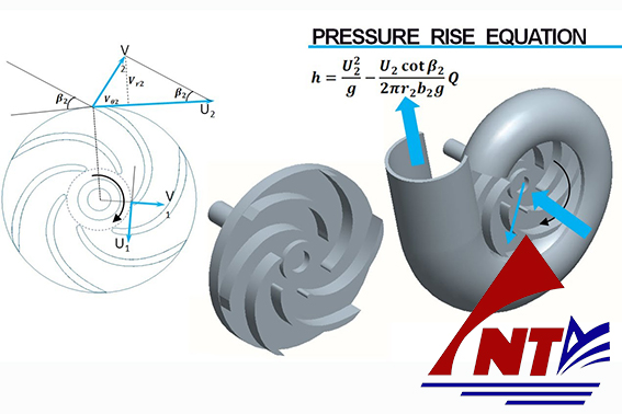
Working principle of centrifugal pump
Such an increase in cross-section is usually obtained by designing the periphery of the housing (tubular aerator) in a spiral with a variable cross-section (usually circular, trapezoidal or rectangular). from 0 to the value of the discharge discharge.
In this way, the kinetic energy stored by the fluid is converted into pressure energy. The pump body, from the part opposite the suction mouth, is closed with a cap. In the central part of the cover, where the shaft passage is located, there is a mechanical sealing chamber. The sealing between the high pressure area (inside the pump body) and the low pressure area (the suction mouth) is achieved through a much reduced clearance created between the impeller and the pump body. The impeller and shaft are cantilevered by two bearings located outside the housing in a special support.
This type of impeller usually has 5 to 7 blades, the minimum size is 125 mm and the largest size is 550 mm.
Impellers have a simple reverse curve with radial motion in the pump, usually with a low number (high head and low flow), while they can have a double reverse curve with semi-axial movement in a numbered pump. high (low head and high volume flow). The blades are completely closed between the center disc and the outer rim disc.
The efficiency of this type of impeller varies from 0.6 for the smallest impeller to 0.83 for the largest impeller.
This type of impeller is suitable for clean liquids or those containing light impurities.
This type of impeller has a reduced number of impellers, varying from 3 to 4, with a minimum size of 270 mm and a maximum size of 450 mm.
The impellers usually have a double curve to the rear and the movement is mainly radial and is fully closed between the center disc and the outer ring disc. The hub is tilted more rearward than the closed propellers described above.
These propellers are relatively much less efficient as the fluid is also unguided due to the limited number of blades and the more rearward tilt of the shaft.
However, these devices allow the creation of internal channels with large openings through which wastewater, containing also rather large suspended solids, can pass.
This type of impeller is fitted with 9 simple curvilinear blades with radial growth.
No outer rim disc is fitted to this impeller, while the center disc, seen in the sections, has a "spoon" motion; The hub was created to give the impeller inside the housing a more tilted rearward position.
This impeller is relatively less efficient because the fluid is not guided like in other types of impeller.
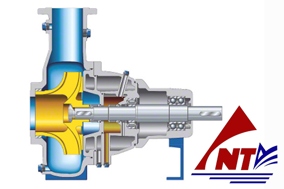
Cross-sectional drawing of centrifugal pump
This is a new impeller for use with dense and highly viscous liquids, or with solutions containing large amounts of dry residue.
The impeller is fitted with two or four blades (on all sizes) depending on the viscosity or consistency of the pumped liquid. Two of these blades, arranged symmetrically in relation to the shaft, are fitted with an appendage extending from the shaft to the suction nozzle with a helical motion.
This type of impeller has no outer ring disc, so a seal of the liquid between each impeller is ensured by an extremely reduced clearance between the impellers and rim wear to the pump body.
This impeller is more efficient than channel and vortex blades and has better suction properties.
Impellers for centrifugal pumps come in a variety of shapes and sizes depending on the required performance and characteristics of the fluid being pumped. All impellers are fitted with special grooves on the back of the hub disc to compensate for axial thrust and reduce pressure in the sealing chamber. The head created by this blowout contrasts with the operating pressure difference between the helix and the seal chamber, pushing the pumped liquid towards the cavity.
Impellers are made from a variety of materials depending on the harshness of the chemical and/or the abrasiveness of the fluid being pumped. All impellers are dynamically balanced before they are fitted to the pump.
2.2. Casing pump
The casing of the centrifugal pump is equipped with a single suction mouth with a single spiral tube aerator available in two versions: with narrow spiral or wide spiral.
Casing pump usually made from the same materials as the impeller, however different materials can be used for specific requirements.
The sealing ring between casing and protective cover is realized through a built-in flat washer to better resist stress caused by pressure and temperature. The materials used for these seals are completely asbestos-free.
The pump body can be manufactured in the heating version (/RR), so there is a chamber to heat the steam up to a pressure of 7 bar and a temperature of 180°C. Pumps of the RN/RNS and RKN/ RKNS is standardized based on the UNI EN 22858 standard and in addition to the ISO 5199 standard.
The housing is manufactured in a way that allows extraction of the impeller without having to remove the housing from the pipeline. The materials used for the enclosure are the same as those used for the enclosure.
The outer zone of the seal chamber can be manufactured in two versions:
a) Cooling version / CHEAP
b) Heating version / RR
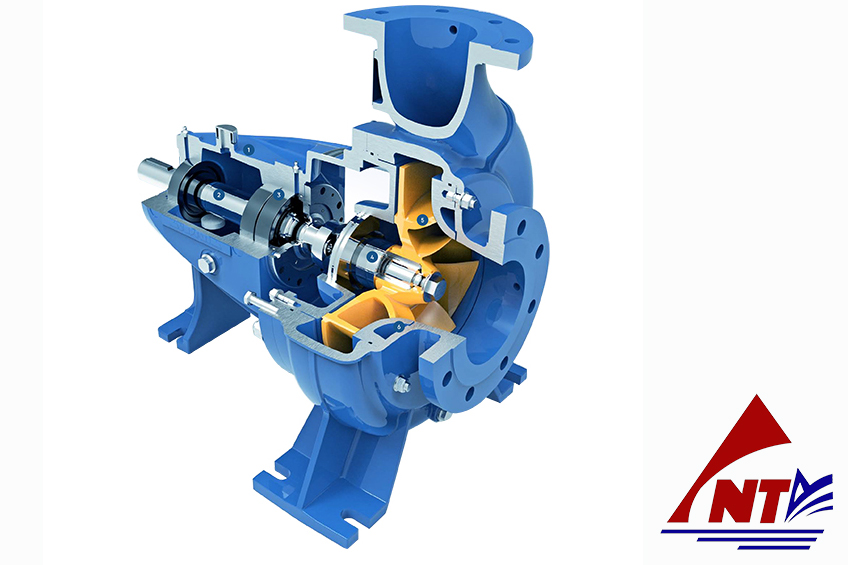
Centrifugal pump construction
The shaft diameter is calculated to minimize deflection in the sealing zone, also under severe operating conditions, and to obtain a critical deflection speed at least two times greater than that supplied to the pump.
Corresponding to the shaft seal, a protective socket (sleeve) is provided to prevent any damage caused by the washer (mainly wear).
The shaft is supported by two roller bearings with a cantilever impeller. The coupling side bearings also support the residual axial thrust of the impeller. The bearings are properly sized for a B10 life of 20,000 hours under the most severe operating conditions planned for the pump.
The function of the shaft seal in a centrifugal pump is to prevent the entry of air into the suction side (for suction pumps) and to eliminate or minimize the possible loss of pressurized liquid on the suction side. pump discharge.
Shaft seals can be of one of three types:
a) braided yarn
b) Mechanical seal
c) Hydrodynamic seals
Hanoi August 31, 2021- Posted by Mr. Water
0964633986
Từ khóa tìm kiếm:
|
NTA PUMP ENGINEERING COMPANY LIMITED C4 Vu Ngoc Phan str, Lang Ha ward, Dong Da Dist, Hanoi city. |
 Tiếng Việt